


- All
- Product Name
- Product Keyword
- Product Model
- Product Summary
- Product Description
- Multi Field Search


High-voltage grid stabilization relies heavily on Static Synchronous Compensators (STATCOMs), but the power electronics driving these systems generate massive, continuous heat loads that threaten operational stability. Thermal bottlenecks in reactive power compensation lead to equipment derating, premature component failure, and compromised grid stability. Traditional air cooling and open-loop water systems struggle with scalability, environmental discharge regulations, and high maintenance overhead. Evaluating the closed-loop water cooled STATCOM architecture serves as the technical standard for high-capacity, mission-critical STATCOM deployments. This approach balances thermal efficiency with environmental, social, and operational realities. Grid operators need reliable reactive power support without the constant threat of thermal shutdowns. By isolating the cooling medium from the outside environment, engineers can push power modules to their maximum ratings while maintaining strict temperature control across all operating conditions.
Reactive power injection and absorption place immense stress on power electronics. Insulated-Gate Bipolar Transistors (IGBTs) and Integrated Gate-Commutated Thyristors (IGCTs) handle massive electrical currents during grid fault ride-through events and steady-state voltage regulation. This continuous switching generates significant thermal energy directly at the semiconductor junction. Heat accumulates rapidly within the module housing. If left unmanaged, this thermal energy causes severe operational bottlenecks and forces the control system to derate the compensator's output to prevent catastrophic failure.
There is a direct correlation between extreme thermal cycling and the degradation of semiconductor lifespans. Material fatigue sets in when components expand and contract repeatedly under fluctuating temperatures. The coefficient of thermal expansion differs between the silicon die, the solder layers, and the copper baseplate. Over time, this mismatch causes solder joint fatigue and wire bond lift-off. You will see increased thermal resistance as the solder layers delaminate, which only accelerates the heating process in a destructive feedback loop.
The success criteria for cooling these systems are strict. Operators must maintain a narrow, stable temperature band under highly variable grid load conditions. Precise thermal control prevents premature failure and ensures the compensator can respond to grid faults instantly. A water cooled static var generator achieves this by pulling heat directly from the baseplate using liquid cold plates, offering a thermal transfer coefficient exponentially higher than forced air.
| Cooling Method | Heat Transfer Coefficient (W/m²K) | Thermal Cycling Stress | Footprint Efficiency |
|---|---|---|---|
| Natural Convection (Air) | 5 - 25 | High | Poor |
| Forced Air Cooling | 25 - 250 | Moderate | Moderate |
| Open-Loop Water | 500 - 3,000 | Low | Good |
| Closed-Loop Liquid | 1,000 - 5,000+ | Very Low | Excellent |
Traditional cooling methodologies present severe limitations at utility scale. Air cooling requires a massive physical footprint. Large fans and extensive heat sinks consume valuable substation real estate. These systems also generate high acoustic noise, complicating deployments near residential zones or urban centers where noise ordinances are strictly enforced. Furthermore, air has a fundamentally limited heat dissipation capacity. It cannot efficiently manage the thermal density of modern, high-capacity reactive power systems without requiring massive volumetric airflow, which in turn draws heavy parasitic power.
Open-loop water systems introduce different operational friction. They rely on continuous water consumption, drawing from local municipal or natural sources. This exposes the internal piping to scaling and biological fouling. Open-loop configurations also face strict environmental regulations regarding heated water discharge. Dumping warm water back into local ecosystems disrupts aquatic life and invites heavy regulatory scrutiny.
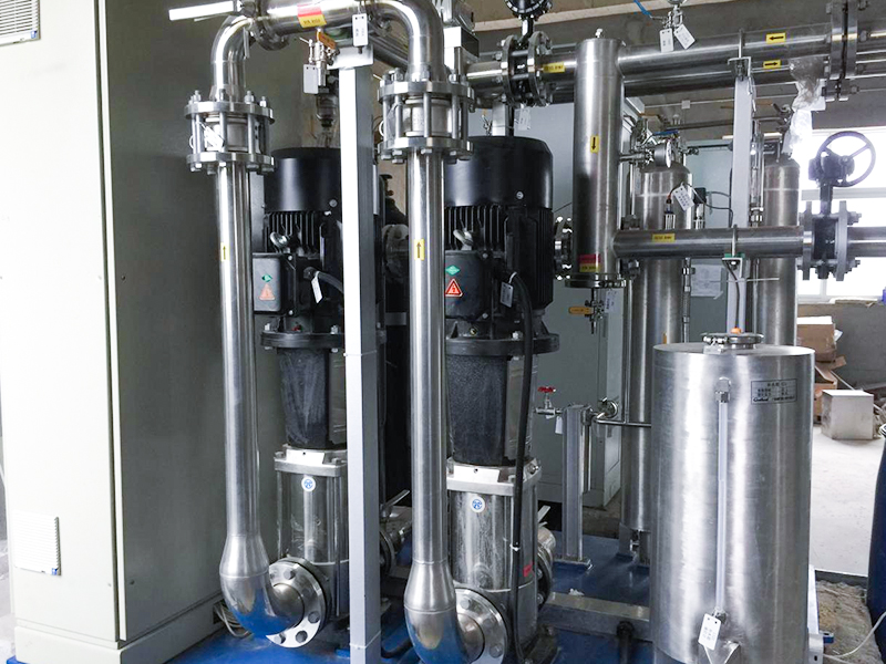
A robust liquid cooling architecture relies on several interconnected hardware components working in unison. The primary mechanical drivers are redundant pump stations. These ensure continuous fluid movement even during maintenance cycles or unexpected mechanical failures. Liquid-to-liquid or liquid-to-air heat exchangers transfer the accumulated thermal energy away from the primary loop and reject it to the secondary cooling medium. Deionization units continuously filter a bypass stream of the fluid to maintain electrical safety. Expansion tanks absorb volumetric pressure changes caused by temperature fluctuations as the compensator cycles from idle to full load.
A closed-loop water cooling system continuously circulates coolant through heat sinks directly attached to the power modules. It transfers heat away without exposing the fluid to the external environment. This mechanical isolation is a massive advantage. A sealed STATCOM cooling system protects sensitive high-voltage components from dust, debris, and external airborne contaminants. You do not have to worry about industrial particulate matter clogging the heat sinks or degrading the dielectric clearances inside the valve hall.
| Component | Primary Function | Maintenance Requirement |
|---|---|---|
| Main Circulation Pumps | Drive coolant through the primary loop and cold plates. | Bearing inspection, seal replacement. |
| Deionization Cartridge | Remove conductive ions from the coolant stream. | Resin bed replacement based on conductivity alarms. |
| Heat Exchanger | Transfer thermal energy to the secondary loop or ambient air. | Periodic flushing, fin cleaning (if air-cooled secondary). |
| Expansion Tank | Maintain system pressure and absorb fluid expansion. | Nitrogen pre-charge verification. |
| Three-Way Valve | Regulate coolant temperature by bypassing the heat exchanger. | Actuator calibration and stroke testing. |
High-voltage environments demand strict fluid specifications. Maintaining low electrical conductivity is an absolute necessity. Operators use highly purified deionized water to prevent arcing and electrical faults. Standard tap water contains mineral ions that conduct electricity, which would cause catastrophic short circuits inside the power modules if a minor leak occurred or if the fluid bridged a high-voltage gap. However, pure deionized water is highly aggressive and corrosive to standard piping materials as it seeks to pull ions from the surrounding metals.
This introduces complex chemical realities. The system requires a precise cocktail of additives to remain stable over a twenty-year lifespan. Antifreeze, typically a high-purity ethylene or propylene glycol blend, prevents freezing in cold climates and alters the boiling point. Biocides stop bacterial growth inside the dark, warm pipes. Corrosion inhibitors passivate the internal metal surfaces, creating a microscopic protective layer that prevents the deionized water from attacking the stainless steel or aluminum components.
This creates a potential chemical time bomb risk. If neglected, glycol breakdown forms acidic byproducts. Biocide degradation leads to organic fouling. These reactions rapidly compromise the dielectric strength of the deionized water, putting the entire compensator at risk. Managing this chemistry requires discipline.
Dynamic flow regulation is necessary for maintaining thermal equilibrium. The cooling station dynamically regulates coolant flow rates and heat exchanger performance. It utilizes variable frequency drive (VFD) pumps and modulating three-way bypass valves. These mechanisms respond instantly to real-time load variations. When the grid demands maximum reactive power during a voltage sag, the pumps accelerate to remove the excess heat. When the system idles, the pumps slow down, reducing parasitic losses and mechanical wear.
System architecture must include N+1 or N+2 redundancy in the pump configuration. This guarantees continuous operation even during an individual component failure. You cannot afford to take a critical grid asset offline for a simple pump seal replacement. The control system automatically rotates the lead and lag pumps to ensure even wear across the mechanical assets. This thermal stability connects directly to overall water cooled STATCOM reliability. By eliminating thermal stress and keeping junction temperatures well below their maximum ratings, operators significantly extend the mean time between failures (MTBF) for the primary power electronics.
Spatial constraints often dictate substation design, especially in urban environments or offshore wind platforms. An indoor water cooled STATCOM requires a significantly reduced physical footprint compared to sprawling outdoor air-cooled capacitor banks and massive heat sinks. Liquid cooling can extract heat efficiently from densely packed power modules. This allows engineers to house the entire system inside compact, climate-controlled enclosures or standard shipping containers.
Facility integration requires careful planning. Structural load considerations are paramount, as water-filled stainless steel piping adds substantial weight to the facility floor. Routing constraints must be mapped to avoid interference with existing high-voltage cabling and busbars. Proper integration with existing substation infrastructure ensures safe maintenance access and streamlined operational workflows. You must design the piping layout to allow for easy venting of trapped air and complete drainage during major maintenance overhauls.
Sustainability is a major driver for modern grid infrastructure. Closed-loop architectures offer a distinct sustainability advantage. They achieve zero water consumption during standard operations. The system requires only occasional replenishment to account for minor evaporation through automatic air vents or small losses during filter changes. This eliminates wastewater discharge and thermal pollution into local water bodies.
Addressing community and regulatory concerns is much easier when you can prove the facility will not drain local aquifers. Mitigating community and permitting anxieties requires clear communication. Public misconceptions often equate any water-cooled facility with data center-style water depletion or chemical runoff. A sealed system eases local environmental impact assessments. It accelerates grid-connection permitting in water-scarce regions by demonstrating responsible resource management. You simply fill the loop once during commissioning, and the fluid remains contained for years.
The most severe risk in liquid cooling is catastrophic system failure caused by water ingress. If conductive fluid reaches high-voltage power electronics, it causes immediate electrical shorting. This destroys the equipment and poses severe safety hazards to personnel. Mitigation requires a multi-layered engineering approach. Specify the requirement for double-walled piping in critical areas directly above the valve hall. Install strategically placed moisture sensors beneath all fluid-carrying components and at the lowest points of the enclosure.
Implement negative pressure system designs where possible. In a negative pressure loop, the pump pulls the coolant through the cold plates rather than pushing it. If a pipe breach occurs, the system draws air into the loop rather than spraying water onto the electronics. Automated fast-acting isolation valves must be integrated to shut down fluid flow instantly upon detecting a pressure drop, a flow mismatch, or a moisture alert from the floor sensors.
Over time, the internal fluid ecosystem can degrade. The primary risk is a gradual loss of dielectric strength or thermal transfer efficiency. This happens due to chemical breakdown, biological growth, or internal pipe scaling. If the corrosion inhibitors fail, microscopic metal particles enter the fluid, increasing its conductivity. If the deionization resin saturates, it can no longer pull these stray ions out of the coolant.
Mitigation relies on constant vigilance. Implement continuous, automated conductivity monitoring tied directly to the facility's SCADA system. Set strict alarm thresholds for fluid resistance. Operators must adhere strictly to vendor-specified coolant replacement schedules. Routine chemical sampling prevents internal corrosion and localized thermal hot spots, ensuring the compensator operates within its designed thermal parameters. You must treat the coolant as a critical component, not just a maintenance afterthought.
Closed-loop water cooling serves as a technical prerequisite for high-capacity, utility-scale STATCOMs where footprint, environmental compliance, and thermal reliability dictate project success. Procurement and engineering teams should prioritize vendors that demonstrate robust N+1 pump redundancy, integrated real-time conductivity monitoring, and transparent chemical maintenance schedules.
A: It is a reactive power compensator that uses a sealed, continuously circulating liquid cooling system. This architecture manages the intense heat generated by power electronics without consuming raw water or discharging heated wastewater into the environment.
A: The sealed nature of the system reuses the exact same coolant indefinitely. Unlike open-loop systems that constantly draw and discharge raw municipal water, a closed-loop configuration requires only minor top-offs for rare maintenance losses.
A: Yes, when engineered correctly. They utilize highly purified deionized water with low electrical conductivity. Additional safety layers include negative pressure piping designs, double-walled containment, and automated leak detection sensors that isolate fluid instantly.
A: Routine maintenance involves checking mechanical pump health and replacing deionizing resin beds. Technicians must also monitor coolant conductivity levels and verify that corrosion inhibitors and biocides remain properly balanced to prevent internal degradation.
A: Deionized water lacks the natural mineral ions that conduct electricity. This high dielectric strength prevents catastrophic short circuits and arcing if the cooling fluid ever comes into close proximity with the high-voltage power modules.
A: Precise temperature control prevents extreme thermal cycling. By maintaining a stable thermal environment, the cooling system prevents mechanical stress, solder fatigue, and premature failure in critical semiconductor components like IGBTs and IGCTs.


