


- All
- Product Name
- Product Keyword
- Product Model
- Product Summary
- Product Description
- Multi Field Search


Thermal management dictates the performance limits of utility-scale reactive power compensation systems. Substation operators face immense pressure to keep operations online and stable. They simply cannot afford unexpected thermal shutdowns. Today, Voltage Source Converter (VSC) and IGBT technologies push incredible power densities. They deliver massive reactive power in highly concentrated packages. Consequently, thermal bottlenecks emerge as the primary constraint limiting continuous operation. Excess heat degrades silicon components quickly.
We will explore how to properly select the right cooling framework for your facility. You will learn to objectively evaluate site constraints, lifecycle costs, and strict reliability mandates. Substation engineers and procurement teams require a clear, evidence-based approach to make this decision. Ultimately, this guide will help you confidently choose the optimal cooled STATCOM tailored to your specific grid demands. We aim to remove the guesswork from complex thermal engineering decisions.
Selection between cooling methods is rarely binary; it is dictated by MVAR capacity requirements, available substation footprint, and ambient environmental conditions.
Water-cooled systems offer superior heat dissipation and compactness for high-capacity deployments but introduce complex fluid maintenance.
Air-cooled systems provide simplified maintenance and lower CAPEX for lower-power applications but demand significantly larger physical footprints.
Redundancy design (e.g., N-1 or N-2 configurations) is mandatory to meet stringent grid code compliance and prevent cascading thermal trips.
Effective thermal control forms the foundation of modern power electronics reliability. Every operational cycle generates significant heat within the converter valves. You must extract this heat rapidly. If you fail to do so, system availability plummets.
Thermal cycling directly impacts IGBT module lifespan. Temperature fluctuations cause distinct layers inside the semiconductor to expand and contract. They do this at different rates. Over time, this mechanical stress induces micro-fractures in the solder joints. These fractures increase electrical resistance, which generates even more heat. This destructive loop ultimately ruins the module. Proper cooling prevents these drastic temperature swings. It stabilizes the internal environment. This stability guarantees higher overall system availability.
A successful cooling strategy must achieve several specific goals simultaneously. It must maintain semiconductor junction temperatures well within safe operating margins. It must do this even under maximum continuous overload conditions. Furthermore, the system must not violate substation noise limits. It also must fit within strictly defined space constraints. Achieving this balance requires careful engineering and precise capacity planning.
Under-specifying cooling capacity carries severe consequences. If the cooling system falls short, the equipment must undergo thermal derating. This means it intentionally lowers its output to survive. You lose crucial reactive power support when the grid needs it most. Additionally, inadequate cooling accelerates premature component failure. This drives up emergency repair costs. Finally, unexpected outages trigger strict grid compliance penalties. Transmission operators heavily fine facilities that fail to deliver promised dynamic reactive power.
Understanding the fundamental mechanisms behind each cooling type is crucial. They operate on entirely different thermal transfer principles.
An Air Cooled Statcom relies on forced ambient air. Massive industrial fans draw outside air through the enclosure. The air passes directly over large aluminum or copper heat sinks. These heat sinks attach physically to the power modules. The air absorbs the heat and exits the building.
This architecture is the best fit for specific scenarios. It excels in low-to-medium voltage installations. It works perfectly for lower capacity ranges. We often see them at remote sites lacking reliable access to treated water. They require a large volume of clean air to function effectively.
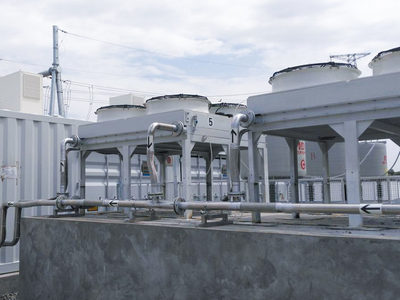
A Water Cooled Statcom employs a completely different thermal path. It uses a closed-loop system circulating ultra-pure deionized water. This liquid flows through metallic cold plates. These plates couple directly to the power electronics. The heated water travels to an external water-to-air heat exchanger. Here, fans cool the water before it returns to the electronics.
This method represents the best fit for demanding applications. High-capacity utility grids heavily depend on it. Offshore wind substations require it due to extreme space limitations. Footprint-constrained industrial facilities also heavily favor this dense cooling method.
The industry constantly explores new thermal technologies. Phase-change and evaporative cooling solutions are emerging slowly. They utilize refrigerants that absorb massive heat as they change from liquid to gas. Currently, they remain niche applications. We maintain a skeptical view regarding their widespread commercial viability today. They lack the decades of proven reliability found in standard water and air systems.
You must weigh three critical physical dimensions before making a choice. These factors often override pure financial considerations.
Space is rarely unlimited in modern substations. Engineers must analyze the MVAR-to-square-meter ratio carefully. This ratio defines how much reactive power you can squeeze into a given area.
High-capacity grids naturally default to liquid cooling. Why does this happen? The reason comes down to basic physics. Routing enough air to cool densely packed IGBT stacks becomes physically impossible at high capacities. The required air ducts would be larger than the building itself. Liquid carries heat roughly 3,000 times more effectively than air by volume. Therefore, water systems allow you to shrink the equipment footprint dramatically.
The local environment heavily influences cooling efficiency. You must account for regional weather patterns.
Temperature Extremes: Air cooling efficiency plummets in high-ambient-temperature regions. If the outside air is already 45°C, it cannot absorb much heat from the electronics.
Air Quality: Environmental contaminants pose a massive threat. Dust, coastal salinity, and industrial pollutants ruin electronics. Air systems require heavy, restrictive filtration. These filters increase static pressure drops. They demand frequent replacement. Liquid systems solve this entirely. They isolate the sensitive electronics inside a sealed environment, safe from external contaminants.
Noise pollution matters deeply, especially near residential zones. Air systems utilize high-velocity industrial fans. These fans push massive volumes of air through tight heat sinks. They generate significant high-frequency noise. Acoustic enclosures can help, but they add bulk and cost.
Conversely, liquid systems utilize pump stations and low-speed heat exchanger fans. These operate at much lower acoustic profiles. The noise remains manageable. They offer a much easier path to acoustic compliance in strict urban environments.
Evaluation Dimension | Air-Cooled Systems | Water-Cooled Systems |
|---|---|---|
Footprint Density | Low (Requires large air ducts and space) | High (Extremely compact modular design) |
Ambient Tolerance | Poor in extreme heat; vulnerable to dust | Excellent; sealed away from outside air |
Acoustic Noise | High (Fast spinning industrial fans) | Low (Quiet pumps, slow external fans) |
You must look beyond the initial purchase order. The true financial impact unfolds over a twenty-year operational lifespan.
Initial costs differ significantly between the two architectures. Liquid systems demand a higher upfront financial commitment. You must purchase specialized pumps, stainless steel piping, and ion exchange resins. You also need complex leak detection sensors. All these components drive up the initial price tag.
Air systems offer a friendlier initial investment. They utilize simpler sheet-metal enclosures. Their fan assemblies cost less to manufacture. They do not require expensive plumbing or complex fluid controls.
Evaluating parasitic power losses reveals a complex picture. Cooling systems consume power to run. We call this parasitic load.
Pumping fluid requires continuous auxiliary power. Pumps run constantly to maintain flow. However, forced air systems are not always cheaper to run. High-volume fans draw massive electrical currents. When air filters foul with dust, static pressure spikes. The fans must spin faster to compensate. Consequently, a dirty air system can easily draw equal or greater parasitic power than a clean liquid loop.
Maintenance realities dictate your ongoing labor costs. Servicing a fluid loop requires specialized knowledge. Technicians must perform regular resin replacements. They must monitor water conductivity strictly. Coolant top-offs and pump seal inspections are mandatory tasks. If conductivity rises, the water becomes electrically conductive, threatening the equipment.
Air systems present simpler maintenance routines. Facility teams focus primarily on mechanical upkeep. They execute routine filter replacements. They perform scheduled fan bearing lubrication. Most general maintenance staff can handle these tasks without specialized fluid training.
Modern grid operators tolerate zero excuses for equipment failure. Reliability depends entirely on intelligent redundancy.
Relying on a single cooling path represents an unacceptable risk. If one pump dies, the entire compensation system trips offline. We prevent this through N-1 and N-2 redundancy designs.
N-1 Redundancy: The system has one backup component. If one pump fails, the secondary pump engages instantly. The system maintains 100% rated capacity.
N-2 Redundancy: The system features two backup components. This provides an extreme layer of security for critical grid nodes.
We apply these principles to both fluid pumps and fan matrices. It ensures continuous thermal extraction despite isolated mechanical failures.
Transmission system operators (TSOs) enforce strict grid codes. They require documented thermal stability for dynamic reactive power services. You cannot simply promise the system will stay cool. You must prove it mathematically. TSOs mandate thermal run-down tests during commissioning. Systems lacking robust cooling fail these tests, delaying grid connection indefinitely.
You must plan for catastrophic failure scenarios. Different systems fail differently. Fluid systems pose the risk of coolant leaks directly inside the electronics cabinet. You mitigate this using highly sensitive moisture detectors. Air systems face fan motor burnouts or severely clogged intakes. You mitigate this using differential pressure switches. These switches alert operators before the airflow drops to critical levels.
Moving from theory to procurement requires a structured evaluation method. Use these practical steps to narrow down your options.
We can establish general MVAR breakpoints to simplify early planning. These thresholds indicate where the transition from air to liquid becomes structurally necessary. Generally, applications below 50 MVAR perform excellently with forced air. The physical footprint remains manageable. Once you cross the 100 MVAR threshold, liquid cooling becomes economically and physically necessary. The air volumes required above 100 MVAR simply become impractical to manage efficiently.
You must build a comprehensive 20-year financial model. Look past the initial equipment quote. Weigh the cost of local substation real estate against the cooling system maintenance schedules. In urban areas, land is expensive. The high upfront cost of a compact liquid system pays for itself by saving precious square meters. In rural areas, land is cheap. A larger air system might make perfect long-term financial sense.
Hold your vendors accountable during the bidding process. Ask them for highly specific empirical data. Do not accept marketing brochures. Request data on coolant conductivity degradation rates over time. Ask for the exact MTBF (Mean Time Between Failures) for their fan arrays. Demand this data based on your site-specific ambient temperature profiles. A fan rated for 100,000 hours at 20°C might only last 40,000 hours at 45°C.
Neither cooling architecture is universally superior across all scenarios. The right choice represents a calculated engineering compromise. You must tailor the solution to your exact site realities.
Your decision matrix is straightforward. Prioritize forced air systems for operational simplicity and lower initial investments. They work best in moderate climates with ample space. Conversely, you should specify liquid systems for maximum power density. They dominate in harsh ambient environments and massive utility deployments.
Do not guess when grid stability is on the line. We strongly prompt engineers to initiate a comprehensive, site-specific thermal load study. Complete this crucial step before you finalize any procurement specifications. Accurate data ensures long-term operational success.
A: A well-maintained liquid cooling loop typically lasts 15 to 20 years. This lifespan heavily depends on strict adherence to maintenance protocols. Facility teams must regularly monitor water conductivity. They must replace deionization resins on schedule. Neglecting these tasks causes internal corrosion, drastically reducing the system's operational life.
A: Upgrading capacity later is highly impractical. Forced air systems rely on rigid physical constraints. The internal heat sinks and external air ducts are sized for a specific thermal load. You cannot easily push more air through existing physical restrictions without creating massive static pressure and acoustic noise.
A: High altitudes significantly reduce air density. Thinner air carries less heat away from the electronics. Installations above 1,000 meters require strict thermal derating. Engineers must oversize the fans and heat sinks to compensate for the lower cooling capacity of thin mountain air.
A: These systems utilize ultra-pure deionized water. This specific water lacks free ions, making it an excellent electrical insulator. In cold climates facing freezing temperatures, engineers sometimes mix the deionized water with specialized industrial glycol. This prevents the pipes from bursting during winter outages.


