 English


Reactive power compensation is no longer a standardized utility requirement. As grid codes tighten and renewable energy penetration increases, dynamic voltage support demands highly specific, site-tailored engineering. Relying on legacy reactive power solutions, such as basic mechanically switched capacitor banks, often leads to grid non-compliance, severe spatial conflicts, and operational instability. Assuming all Static Synchronous Compensators perform identically is an engineering mistake that jeopardizes entire substation projects.
Evaluating modern reactive power solutions requires moving far beyond basic MVAR ratings. Decision-makers must analyze specific converter topologies, thermal management systems, and environmental enclosures. This rigorous evaluation ensures the technology aligns perfectly with site-specific grid demands, fault ride-through requirements, and local environmental extremes. We will explore the different types of STATCOM architectures available today. You will learn how to match converter topologies, cooling methods, and physical enclosures to your exact project requirements, ensuring long-term grid stability.
STATCOM architectures vary fundamentally by topology (e.g., modular multilevel vs. standard voltage-bridge) and connection configuration, directly impacting harmonic performance and fault ride-through.
Cooling methodology dictates both the operational footprint and the long-term maintenance overhead of the installation.
Environmental deployment constraints dictate the choice between containerized, building-housed, or open-air configurations.
Selecting a qualified system integrator requires vetting their specific experience with your required grid code, control system integration, and hardware-in-the-loop testing capabilities.
Traditional reactive power management relies heavily on mechanically switched capacitor (MSC) banks and reactor banks. These legacy systems switch in discrete, pre-defined steps. This sluggish, step-based response frequently causes severe voltage overshoots or undershoots during sudden load rejections or generation drops. Field engineers often observe that the mechanical wear and tear on physical breakers during frequent switching events leads to high failure rates and extended maintenance outages. In stark contrast, modern power electronics provide continuous, sub-cycle reactive power injection or absorption. They stabilize the grid instantly without relying on moving mechanical parts. This dynamic capability mitigates rapid voltage fluctuations caused by intermittent renewable generation, preventing nuisance tripping of sensitive plant equipment.
The operational differences between a Static VAR Compensator (SVC) and a modern converter-based solution become glaringly obvious during severe grid faults. SVCs utilize thyristor-controlled reactors (TCR) and thyristor-switched capacitors (TSC). Because they rely on passive components, an SVC's reactive power output is directly proportional to the square of the grid voltage. When grid voltage drops during a fault, the SVC's ability to provide reactive support collapses quadratically just when the grid needs it most.
Advanced converters act as true voltage sources. They inject their maximum rated reactive current even at severely depressed system voltages. This flat voltage-current characteristic ensures robust low-voltage ride-through (LVRT) performance, preventing localized voltage sags from cascading into wider regional blackouts. Site commissioning tests consistently demonstrate that converter-based systems maintain full reactive current output down to 0.1 per unit (pu) voltage, whereas SVC output drops to near zero.
Performance Metric | Legacy SVC | Modern STATCOM |
|---|---|---|
Response Time | 2 to 3 cycles (30-50 ms) | Sub-cycle (<10 ms) |
Low Voltage Output | Drops quadratically with voltage | Maintains full reactive current |
Harmonic Generation | High (requires large passive filters) | Low (especially in MMC topologies) |
Active Damping | Limited capability | Highly effective for SSR/SSCI |
Footprint | Extensive (large reactors and filters) | Compact (high power density) |
Wind and solar plants introduce complex stability challenges, particularly regarding sub-synchronous resonance (SSR) and sub-synchronous control interactions (SSCI). Legacy SVCs struggle to damp these high-frequency oscillations and can sometimes exacerbate them due to their passive filter networks. Modern converter topologies offer superior active damping characteristics. Through advanced control algorithms, they inject counter-oscillatory currents to neutralize SSR. Grid operators now mandate these active damping capabilities as the strict standard for integrating large-scale inverter-based resources (IBR) into weak grids.
Substation real estate is highly constrained, particularly in brownfield upgrades where land expansion is physically impossible. SVCs require massive physical footprints to house bulky thyristor valves, large air-core reactors, and extensive passive harmonic filter banks. Advanced converter solutions eliminate the need for large passive components. This spatial efficiency allows engineers to deploy high-capacity reactive support within tight property lines, avoiding complex land acquisition delays, environmental permitting hurdles, and extensive civil engineering modifications.
While the underlying Insulated-Gate Bipolar Transistor (IGBT) technology is universally superior to legacy thyristor-based FACTS (Flexible AC Transmission Systems) devices, these systems are not interchangeable commodities. Internal configurations, switching frequencies, and control hardware vary wildly between manufacturers. You must match the specific internal architecture to your operational environment, load profile, and regional grid code requirements to achieve reliable performance. A system designed for a stable transmission corridor will fail if deployed to mitigate severe flicker in an industrial steel mill.
Early generations of reactive power compensators utilized two-level or three-level Voltage-Source Converter (VSC) topologies. While effective, these traditional voltage-bridge circuits generate significant harmonic distortion due to their high-frequency switching blocks. To meet utility power quality standards, traditional VSCs require heavy AC harmonic filters, which consume space and introduce resonance risks.
The industry has decisively shifted toward Modular Multilevel Converter (MMC) topologies for transmission-level applications. MMC architectures stack dozens or hundreds of independent submodules in series. By switching these submodules in a cascaded sequence, the MMC generates a nearly perfect sinusoidal voltage waveform. This eliminates the need for bulky AC filters. Furthermore, MMC topologies operate at lower individual switching frequencies, drastically reducing switching losses and thermal stress on the IGBTs.
The modular nature provides built-in redundancy through specific engineering mechanisms:
N+1 or N+2 Redundancy: Systems are designed with extra submodules per phase.
High-Speed Bypass: If a single submodule fails, a mechanical or solid-state bypass switch activates in microseconds.
Continuous Operation: The control system recalculates the switching sequence instantly, allowing the unit to remain online without interruption or derating.
Hot-Swappable Maintenance: Defective submodules can be isolated and replaced during scheduled maintenance windows without requiring a complete system teardown.
The connection configuration of the converter phases dictates its ability to handle unbalanced loads. A standard star (or wye) connected system is highly effective for balanced utility transmission networks. However, industrial environments present severe phase imbalances. Heavy traction networks, mining hoists, and electric arc furnaces draw asymmetrical currents, causing localized voltage unbalance that degrades equipment life and triggers utility penalties.
For these demanding applications, engineers specify a delta connected STATCOM. The delta configuration allows the control system to manage reactive power independently across each phase. It provides a closed loop for zero-sequence currents to circulate internally. This traps the harmful unbalance currents within the converter, preventing them from propagating upstream into the wider utility grid and violating point-of-common-coupling (PCC) compliance limits.
Classification depends heavily on the voltage level and primary application. A Distribution STATCOM (DSTATCOM) typically operates at medium or low voltages, ranging from 480V up to 35kV. Its primary mission is mitigating localized power quality issues. DSTATCOMs act as active power filters, neutralizing harmonic distortion, mitigating rapid voltage flicker from industrial machinery, and balancing uneven phase loads within a specific facility.
Transmission-class systems connect to high-voltage networks, often exceeding 110kV via step-up transformers. Their control algorithms focus on bulk grid stability. They manage regional voltage regulation, provide massive reactive current injection during transmission line faults, and increase the steady-state power transfer capacity of existing high-voltage corridors by maintaining a flat voltage profile across long distances.
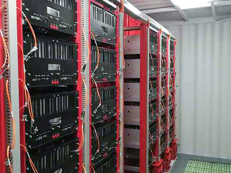
Power electronics generate substantial heat during continuous switching operations. Managing the junction temperature of the IGBTs prevents thermal runaway and component failure. The chosen cooling methodology dictates the physical layout, maintenance schedule, and overall reliability of the installation.
An air cooled STATCOM utilizes high-velocity fans to force ambient air across extruded aluminum heatsinks attached directly to the power modules. This method is standard for medium-voltage and lower-capacity installations.
Mechanical Simplicity: There are no pumps to fail, no plumbing to leak, and zero risk of coolant freezing in sub-zero climates. Maintenance is largely restricted to replacing air filters, cleaning heatsink fins, and periodically inspecting fan bearings.
Spatial Requirements: Air is a relatively poor thermal conductor. To achieve the necessary heat dissipation, the power modules must be spaced further apart, resulting in a larger physical footprint.
Acoustic Challenges: The high-velocity fans generate significant acoustic noise. Deploying air-cooled systems near residential neighborhoods requires acoustic baffles, specialized sound-dampening enclosures, or strict adherence to property line noise ordinances.
For high-capacity transmission applications, thermal loads exceed the capabilities of forced air. A water cooled STATCOM circulates deionized water, or a water-glycol mix, through cold plates mounted directly against the IGBT modules.
Thermal Efficiency: Liquid cooling offers exceptional thermal conductivity. Engineers pack power modules tightly together, achieving immense power density and a highly compact footprint. It is the only viable option for ultra-high MVAR ratings where spatial constraints are strict.
System Complexity: The mechanical complexity is high. The system requires redundant pumping stations, expansion tanks, and external heat exchangers.
Purity Monitoring: You must strictly monitor coolant purity. Any increase in water conductivity causes catastrophic electrical arcing across the high-voltage components. Maintenance requires specialized plumbing expertise, regular replacement of deionizing resin beds, and continuous sensor calibration.
Feature | Air Cooled Systems | Water Cooled Systems |
|---|---|---|
Power Density | Low to Medium | Extremely High |
Footprint | Large (requires airflow clearance) | Compact |
Maintenance Complexity | Low (Filter and fan replacements) | High (Resin beds, pump maintenance, fluid checks) |
Acoustic Noise | High (due to high-velocity fans) | Low to Moderate (pump and heat exchanger noise) |
Leak Risk | Zero | Present (requires strict monitoring) |
The physical environment surrounding the substation heavily influences the enclosure strategy. Power electronics are highly sensitive to moisture, dust, and temperature extremes. Selecting the right housing ensures continuous operation and protects the internal components from accelerated degradation.
An indoor STATCOM is deployed within a purpose-built concrete building or a prefabricated, containerized E-house. This approach isolates the sensitive electronics from harsh external elements.
Environmental Protection: Indoor configurations are mandatory in coastal regions with heavy salt fog, desert environments with abrasive sandstorms, or heavy industrial zones with conductive airborne dust.
Climate Control: Heavy-duty HVAC systems maintain a tightly controlled ambient temperature and humidity level, optimizing the lifespan of the IGBTs, DC link capacitors, and control boards.
Security and Access: Enclosed buildings offer superior physical security against vandalism and wildlife intrusion. They allow maintenance personnel to service the equipment safely during severe weather conditions.
Fire Suppression: Indoor setups allow for the integration of advanced clean-agent fire suppression systems, such as NOVEC 1230 or FM-200. These systems extinguish electrical fires rapidly without leaving damaging residue on the circuit boards.
When substation space permits and environmental conditions are moderate, an outdoor STATCOM can be deployed. These systems utilize heavy-duty, weather-resistant enclosures directly mounted on concrete pads.
Enclosure Ratings: Outdoor cabinets must meet strict IP54, IP55, or NEMA 3R/4X ratings to prevent water and dust ingress. They feature double-walled construction to mitigate solar heat gain.
Thermal Derating: Engineers must account for extreme ambient temperatures. In high-heat environments, the system requires thermal derating, meaning it cannot operate at its absolute maximum capacity during peak summer temperatures without risking thermal shutdown.
Condensation Management: Outdoor cabinets include internal anti-condensation heaters. These heaters activate during temperature drops to prevent moisture from forming on the high-voltage busbars, which leads to flashovers.
Civil Works: While outdoor systems avoid the construction of a building, they require larger concrete footprints to accommodate the weatherproof housings and maintain safe electrical clearances between the cabinets and other substation infrastructure.
Procurement begins with a rigorous analysis of local grid codes, such as IEEE 2800 or ENTSO-E. Define success criteria based on the required response time. Modern grid codes demand sub-cycle reaction times during fault ride-through (FRT) events. The system must detect a voltage sag and inject reactive current almost instantly to support grid voltage.
You must verify the required k-factor for reactive current injection. Different utilities mandate specific ratios of reactive current injection relative to the depth of the voltage dip. Evaluate the system's ability to recover active power immediately after the fault clears, preventing secondary frequency dips in renewable energy applications. Field testing during commissioning will validate these exact parameters against the utility's dynamic models.
Initial layout decisions lock in your future expansion capabilities. As renewable integration increases or industrial facilities expand, reactive power demands inevitably grow. Evaluate how easily the proposed system scales. Modular MMC designs allow you to add extra submodules later to increase the voltage rating or MVAR capacity.
Ensure that the initial civil foundations, cable trenches, and cooling system capacities are sized to handle future upgrades. Failing to plan for scalability forces utilities to execute complete, disruptive site teardowns when grid requirements evolve. Site engineers should map out the physical footprint for a potential 20% to 30% capacity expansion during the initial civil design phase.
The reliability of your reactive power asset is directly tied to the quality of its internal components. Power electronics rely heavily on specialized IGBTs, IGCTs, and high-voltage DC film capacitors. Assess your STATCOM supplier for robust supply chain practices and component traceability.
Demand explicit guarantees for long-term lifecycle support. Obsolescence management is a critical risk factor for utility assets expected to operate for 20 to 30 years. The supplier must demonstrate a clear roadmap for sourcing replacement power modules and control boards decades after the initial commissioning date. Verify that they source their semiconductor components from tier-1 foundries with proven industrial track records.
Hardware capabilities are useless without seamless control integration. Interfacing proprietary converter controllers with legacy utility SCADA or Energy Management Systems (EMS) is notoriously complex and prone to delays. The control system must communicate flawlessly with remote dispatch centers to execute voltage setpoint changes.
Demand open, standardized communication protocols such as IEC 61850, including GOOSE messaging for high-speed protection, DNP3, or IEC 60870-5-104. Ensure the supplier has proven, documented experience mapping their internal data points to your specific control architecture, preventing communication bottlenecks during grid emergencies.
Never accept site delivery of a dynamic reactive power system without rigorous, documented testing. Outline exactly what technical milestones the supplier must achieve during the Factory Acceptance Testing (FAT) phase. Standard steady-state testing is insufficient for dynamic grid assets.
You must mandate Hardware-in-the-Loop (HIL) testing. HIL utilizes real-time digital simulators, like RTDS or OPAL-RT, to interface the actual physical control boards with a simulated model of your specific grid. This allows engineers to subject the controllers to severe simulated grid faults, frequency deviations, and SSR events. Validating damping controls and fault ride-through behavior in a controlled laboratory environment prevents catastrophic software failures during live grid commissioning.
Dynamic reactive power compensators are highly engineered, site-specific assets. Treating them as interchangeable commodities inevitably leads to project overruns, excessive maintenance demands, spatial conflicts, or outright failure to meet stringent grid compliance standards. Success requires matching the internal topology, cooling mechanism, and physical enclosure to your exact operational reality.
Commission a comprehensive, site-specific power system study to define exact steady-state and dynamic reactive power requirements before engaging vendors.
Audit your available substation footprint to determine the viable cooling methodology and enclosure strategy based on local environmental severity.
Issue a detailed Request for Proposal (RFP) that explicitly mandates Hardware-in-the-Loop (HIL) testing and open SCADA communication protocols.
Verify the supplier's long-term obsolescence management plan for critical power electronics components to ensure a 20-year operational lifespan.
A: A STATCOM operates at high transmission voltage levels to provide bulk grid stability, regional voltage regulation, and robust fault ride-through support. A DSTATCOM operates at medium or low voltages. It focuses on resolving local power quality issues, such as mitigating rapid voltage flicker, balancing uneven phase loads, and actively filtering harmonics.
A: Specify a delta connected configuration when dealing with severely unbalanced industrial loads, such as electric arc furnaces or heavy traction networks. The delta loop allows for independent phase control and traps zero-sequence currents internally, preventing them from propagating into the wider utility grid and violating power quality standards.
A: Indoor setups require structural foundations for purpose-built buildings or E-houses, alongside heavy-duty HVAC installations and fire suppression systems. Outdoor setups require robust concrete pads designed to support heavy, weatherproof IP/NEMA-rated enclosures. Outdoor civil works must also account for wider spacing to meet strict electrical clearance and environmental derating standards.
A: Traditional capacitor banks and SVCs rely on grid voltage; their reactive power output drops quadratically as system voltage falls. A converter-based system acts as an independent voltage source. It injects its maximum rated reactive current into the grid even when system voltages are severely depressed, providing vastly superior fault recovery.
A: Maintenance focuses heavily on the liquid cooling loop. Technicians must regularly monitor coolant purity to prevent conductivity spikes that cause electrical arcing. Routine tasks include inspecting redundant pumps, replacing deionizing resin beds, checking for micro-leaks in the plumbing, and verifying the integrity of the external heat exchangers.
A: Evaluate suppliers based on their proven ability to meet specific local grid codes and their supply chain transparency for sourcing IGBTs. Demand evidence of successful control system integration with legacy SCADA platforms. Verify their capability to perform rigorous Hardware-in-the-Loop (HIL) testing during Factory Acceptance Testing to simulate grid faults.


