 English


Industrial facilities and critical infrastructure face mounting financial losses from grid instability. Millisecond-level power disturbances routinely halt production lines, scrap raw materials, and damage sensitive equipment. Facility engineers and plant managers must deploy targeted defenses, but they often struggle to align specific grid disturbances with the correct custom power device topology. You must determine the exact source of the problem before specifying hardware. Facilities need to decide whether they require a customer-side defense against utility grid faults or a solution to prevent facility-generated load fluctuations from polluting the local network.
This guide provides a technical evaluation of STATCOM (Static Synchronous Compensator) and DVR (Dynamic Voltage Restorer) technologies. We detail their operational mechanics, physical footprint requirements, and implementation realities. You will learn how to select the right system based on your facility's specific power quality profile, load sensitivity, and operational demands.
Topology Dictates Function: A DVR is a series-connected device designed primarily for rapid voltage sag protection, while a STATCOM is a shunt-connected device built for reactive power compensation and steady-state voltage regulation.
Disturbance Targeting (Utility vs. Customer Side): Choose a DVR to protect sensitive downstream loads from upstream utility grid faults (sags/swells); choose a STATCOM (or D-STATCOM) to stabilize the grid from disturbances generated by your own non-linear, unbalanced, or fluctuating loads.
Energy Storage Requirements: DVRs typically require substantial real energy storage (batteries or supercapacitors) to inject active power during deep sags, whereas STATCOMs primarily rely on DC link capacitors to exchange reactive power.
Cost vs. Risk: Selecting between the two requires a precise power quality audit to ensure capital expenditure aligns with the actual cost of downtime caused by the specific, measured grid anomaly.
Selecting effective power quality solutions requires a precise understanding of the electrical environment. Engineers cannot specify mitigation equipment without first quantifying the exact nature of the grid disturbances affecting the facility. We see many plants install the wrong hardware because they skipped baseline monitoring and relied on assumptions.
Baseline power quality monitoring categorizes grid issues into two distinct groups. Transient events include voltage sags, swells, and momentary interruptions. These occur rapidly, often due to lightning strikes or utility fault clearing, and resolve quickly but cause immediate equipment failure. Steady-state issues include poor power factor, continuous voltage flicker, phase unbalancing, and harmonic distortion. These chronic conditions degrade equipment lifespans, overheat transformers, and trigger utility penalties. Identifying which category dominates your electrical network dictates the required hardware topology.
Facility managers must map the ITIC (Information Technology Industry Council) or CBEMA curve of all critical facility equipment. This mapping determines the exact voltage tolerance and ride-through requirements of sensitive loads. Programmable Logic Controllers (PLCs), variable frequency drives (VFDs), and robotic controllers often drop out at specific voltage thresholds. For example, a standard VFD will trip on a DC bus undervoltage fault if the incoming supply drops below 85% of nominal for more than one cycle. Understanding these dropout points allows engineers to specify the exact response time and compensation capacity required from the mitigation device.
Meeting utility grid codes remains a primary driver for deploying active compensation systems. Utilities enforce strict standards, such as IEEE 519 for harmonic limits, to protect the wider grid from pollution. Facilities generating heavy reactive power loads face severe financial penalties for poor power factor, often billed on peak kVA demand rather than actual kW usage. Non-compliance leads to heavy fines or forced disconnection from the utility network. Mitigation equipment must ensure the facility remains within these strict operational boundaries at the point of common coupling (PCC).
Install Class A power quality meters at the main incoming utility feed and at the specific sub-panels feeding sensitive equipment.
Configure the meters to capture high-resolution waveform data for any voltage deviation exceeding 5% of nominal.
Log data continuously for a minimum of 30 days to capture a representative sample of utility grid behavior and internal plant load cycles.
Cross-reference the timestamped power quality events with the facility's maintenance logs to correlate grid disturbances with actual machine downtime.
Generate a load profile report detailing the peak reactive power demand and the maximum harmonic current distortion.
A STATCOM represents an advanced class of flexible AC transmission system (FACTS) devices. It provides rapid, continuous control of reactive power to stabilize grid voltage and improve overall power quality across heavy industrial networks.
The STATCOM utilizes a parallel, or shunt, grid connection. It operates as a controlled reactive current source. The core architecture features a Voltage Source Converter (VSC) paired with a DC link capacitor. The VSC utilizes high-speed insulated-gate bipolar transistors (IGBTs) and Pulse Width Modulation (PWM) to synthesize a waveform that leads or lags the grid voltage. This configuration allows the system to inject or absorb reactive current independent of the prevailing grid voltage. Unlike traditional capacitor banks, the STATCOM maintains full compensation capacity even during severe voltage depressions.
The D-STATCOM (Distribution STATCOM) serves as the distribution-level variant of this technology. It generates a controllable AC voltage source via high-speed feedback control. This specific variant addresses localized power quality issues at the facility level. It focuses on correcting load-generated anomalies rather than managing transmission-level grid stability.
Industrial networks with heavy, fluctuating loads rely heavily on STATCOM voltage regulation. The system stabilizes voltage profiles across networks burdened by electric arc furnaces, large motor starts, and mining hoists. It mitigates the severe voltage dips caused by these sudden load changes, preventing adjacent equipment from tripping offline.
Beyond voltage stabilization, the STATCOM excels at improving overall power factor. It acts as a highly dynamic source of reactive power compensation. The system also mitigates continuous voltage flicker and corrects load phase unbalancing, ensuring a stable, symmetrical power supply for sensitive downstream equipment.
Managing the thermal load of high-power IGBTs dictates the physical layout of the installation. Air-cooled systems are suitable for lower power ratings but require massive HVAC infrastructure in the electrical room to manage the heat rejection. Filters require monthly replacement in dusty industrial environments. Water-cooled systems are mandatory for high-capacity units. They utilize deionized water loops pumped through heat sinks directly attached to the IGBT modules. This requires external heat exchangers, redundant pump skids, and strict water conductivity monitoring.
Despite its versatility, the STATCOM possesses distinct limitations. The system cannot inject active power without the addition of an external energy storage system. It primarily exchanges reactive power. Consequently, it is less effective at mitigating deep, prolonged voltage sags compared to series-connected devices. Furthermore, the power electronics require a substantial physical footprint. Facility engineers must account for the rigorous thermal management, active cooling requirements, and the physical space needed for the phase reactors and VSC modules.
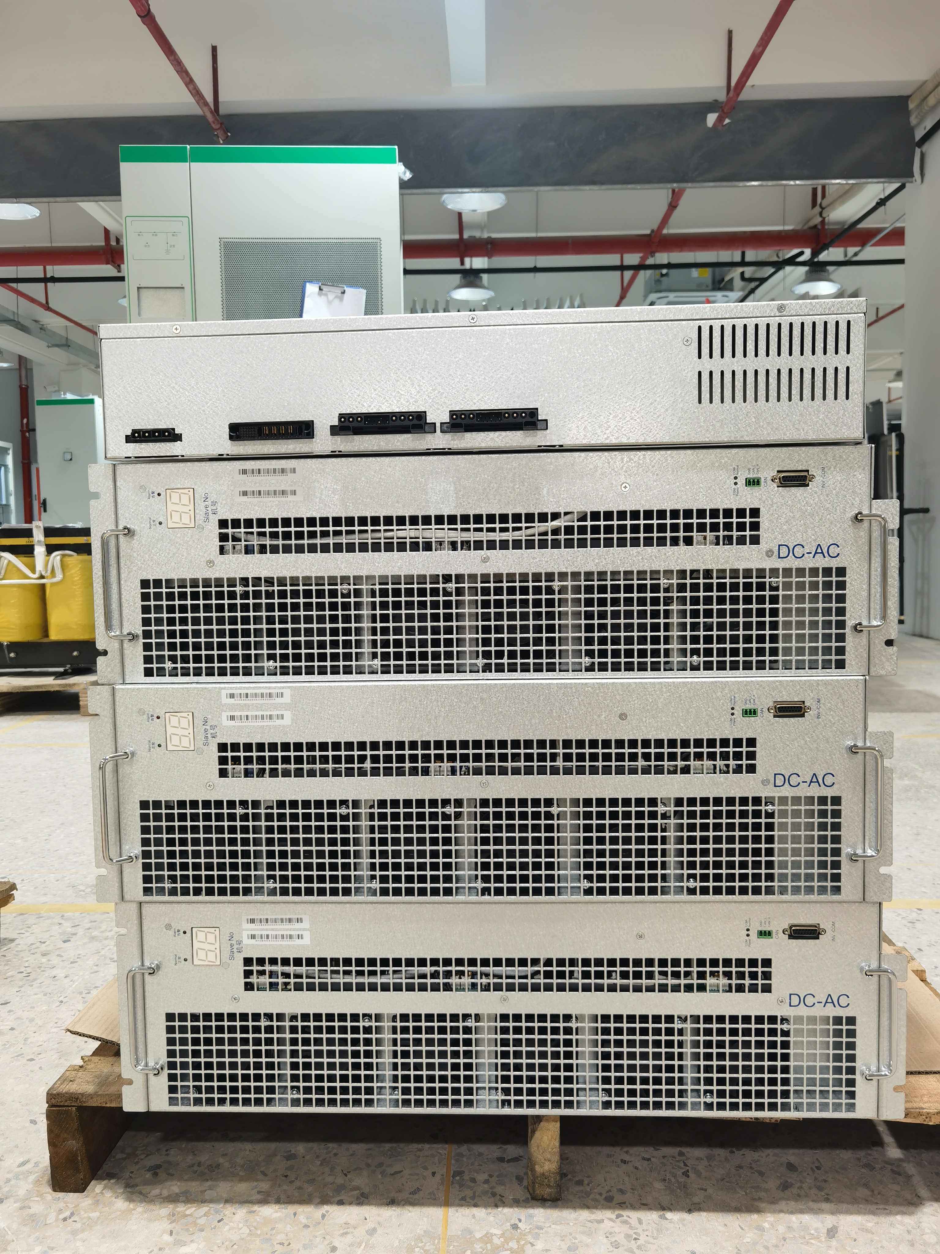
The DVR functions as a highly specialized, series-connected protection device. It shields sensitive industrial loads from severe upstream grid disturbances, acting as an active voltage firewall between the utility and the plant floor.
A DVR connects in series with the grid via an injection transformer. The dynamic voltage regulator continuously monitors the upstream supply voltage. When it detects a voltage anomaly, the internal inverters instantly synthesize and inject the exact missing voltage vector. It precisely matches both magnitude and phase angle. This rapid injection maintains a perfect, uninterrupted sine wave at the load terminals, completely masking the upstream fault from the sensitive equipment.
The primary use case for a DVR is rapid voltage sag protection. It acts as a dedicated customer-side shield. Highly sensitive manufacturing processes depend on this protection. Semiconductor fabrication plants, continuous extrusion lines, and automated pharmaceutical packaging facilities cannot tolerate even millisecond-level sags. The DVR prevents utility-side voltage sags and short-term interruptions from crashing these critical production lines and ruining batches of raw material.
Storage Type | Typical Ride-Through Duration | Footprint Requirement | Maintenance Intensity |
|---|---|---|---|
Supercapacitors | 1 to 3 seconds | Moderate | Low (No chemical degradation) |
Lithium-Ion Batteries | 30 seconds to 5 minutes | Large (Requires dedicated racks) | High (Strict HVAC and fire suppression) |
Flywheels | 10 to 30 seconds | Very Large | High (Bearing maintenance) |
Series-connected devices present a unique choke point in the electrical network. If a downstream fault occurs, the massive short-circuit current will destroy the DVR inverters instantly. We install ultra-fast thyristor bypass switches across the series injection transformer. These detect overcurrents in microseconds and shunt the fault current away from the power electronics. A parallel mechanical circuit breaker operates in tandem with the thyristors to carry the fault current if the event lasts longer than a few cycles, allowing the upstream protection relays to clear the fault safely.
The DVR relies heavily on an external energy storage system (ESS) to function during deep sags. Because it must inject active power to restore the missing voltage, it requires batteries, supercapacitors, or flywheels. This dependency strictly limits the duration of protection based on the ESS capacity. Additionally, the series connection introduces fault current limitations. The system requires robust, high-speed bypass mechanisms to protect the DVR inverters during severe downstream short circuits, adding complexity to the overall switchgear lineup.
When comparing STATCOM vs DVR, engineers must evaluate distinct topological differences. Each system interacts with the grid in fundamentally different ways, dictating their suitability for specific power quality problems.
The STATCOM utilizes shunt injection of current, sitting parallel to the load. It draws or supplies reactive current to influence the voltage at the point of connection. The DVR utilizes series injection of voltage, sitting inline with the load. It directly adds voltage to the supply line. Engineers must carefully evaluate how each topology interacts with existing facility protection schemes. Series devices require complex bypass coordination, while shunt devices can influence the operation of traditional overcurrent relays by altering the fault current paths.
Both technologies utilize VSC-based architectures, delivering sub-cycle response times. However, they handle disturbances differently. The DVR demonstrates absolute superiority in transient sag mitigation. It instantly forces the load voltage back to nominal levels during a utility fault. The STATCOM demonstrates superiority in continuous reactive power management. It excels at stabilizing the grid during sudden, massive load changes that require rapid reactive support, such as starting a 5,000 horsepower compressor motor.
These systems address secondary power quality problems with varying degrees of success. D-STATCOMs excel at actively filtering load-generated harmonic distortions. They inject counter-harmonics to cancel out non-linear load currents and continuously correct phase unbalance. DVRs do not primarily filter load harmonics. They focus strictly on fundamental voltage magnitude and phase restoration resulting from upstream utility faults.
Deploying a medium voltage STATCOM is highly practical for facility-wide or substation-level compensation. These units connect directly at the Point of Common Coupling (PCC) to manage massive industrial loads. Scaling DVRs to high voltage and high current levels presents significant challenges. The constraints, physical size, and extreme costs of medium voltage series injection transformers make large-scale DVR deployments highly complex and expensive.
Feature | STATCOM (Static Synchronous Compensator) | DVR (Dynamic Voltage Restorer) |
|---|---|---|
Grid Connection | Shunt (Parallel) | Series (Inline via Transformer) |
Primary Function | Reactive power compensation, load balancing | Active voltage sag and swell mitigation |
Injection Mechanism | Injects/absorbs reactive current | Injects missing voltage vector (magnitude/phase) |
Energy Storage | Minimal (DC link capacitors) | Substantial (Batteries, Supercapacitors) |
Target Disturbance | Facility-generated steady-state issues | Utility-generated transient voltage sags |
Selecting the correct power quality device requires a rigorous financial and operational assessment. The initial equipment cost represents only one fraction of the overall financial equation. Engineers must look at the entire lifecycle of the installation.
Engineers must calculate the return on investment for each system. This requires comparing equipment and installation costs directly against the financial impact of unmitigated power quality events. A single severe voltage sag can ruin a batch of semiconductor wafers, costing millions in scrapped material, labor overtime for cleanup, and missed shipping deadlines. In this scenario, the high CapEx of a DVR is immediately justified. Conversely, chronic power factor penalties from the utility can drain operational budgets monthly, justifying the deployment of a STATCOM to eliminate the recurring fines.
Lifecycle maintenance differs significantly between the two technologies. A STATCOM requires ongoing maintenance of its cooling systems, pump skids, and periodic inspection of DC link capacitors. A DVR involves managing energy storage degradation. Batteries require strict environmental controls, fire suppression systems, and eventual replacement, adding heavily to long-term operational costs. Furthermore, physical space requirements vary. STATCOMs can often be housed in standard electrical rooms or outdoor substations, while DVRs require additional footprint for their extensive energy storage racks and series transformers.
Integrating active power electronics into legacy electrical networks introduces specific engineering risks. Proper planning, site preparation, and system studies are mandatory to prevent operational failures.
Introducing active compensation devices creates the risk of nuisance tripping or protection blinding. Shunt devices can alter fault current paths, potentially causing legacy overcurrent relays to misoperate. Series devices can mask downstream faults from upstream breakers, altering the zone of protection. To mitigate this risk, facilities must mandate comprehensive short-circuit and protection coordination studies prior to specification. Relay settings often require recalculation to ensure safe, coordinated tripping during fault conditions.
Improper sizing renders power quality equipment useless during severe events. Undersizing a DVR results in inadequate energy storage, causing the system to drop the load before the utility sag clears. Undersizing a STATCOM results in insufficient MVAR capacity, failing to stabilize the voltage during peak load swings. To mitigate this, engineers must utilize high-resolution, long-term power quality logging. Capturing true worst-case transient events and sudden load changes over several weeks is essential before finalizing equipment sizing.
You cannot simply energize these systems and walk away. The SAT phase requires rigorous validation. We use massive resistive load banks to simulate sudden factory load changes, verifying the STATCOM's sub-cycle reactive power injection. We utilize specialized grid simulators to artificially drop the incoming voltage, proving the DVR can synthesize the missing voltage vector before the downstream PLCs drop out. We also measure the Total Harmonic Distortion (THD) at the PCC before and after energization to ensure the active filtering algorithms comply with IEEE 519 limits.
Modern power quality devices act as high-resolution grid monitors. We integrate the device controllers directly into the plant SCADA system using standard protocols like Modbus TCP/IP and IEC 61850. The internal controllers capture oscillography data during grid events. Engineers download these COMTRADE files to analyze the exact phase angles and voltage magnitudes during a utility fault, allowing for continuous optimization of the plant's electrical defenses.
Install Class A power quality analyzers at the main incoming feed for a minimum of 30 days to capture empirical grid disturbance data.
Map the specific voltage tolerance curves and ride-through capabilities of all critical facility loads using manufacturer ITIC data.
Execute a comprehensive grid protection coordination study to ensure the safe integration of active power electronics into your legacy network.
Request vendor proposals that include guaranteed response times and specific thermal management requirements for the proposed installation environment.
A: A STATCOM uses a shunt connection to inject reactive current, providing reactive power compensation and stabilizing steady-state voltage for facility-generated issues. A DVR uses a series connection to inject active voltage, providing rapid protection against utility-generated voltage sags to shield sensitive customer loads.
A: A STATCOM provides limited voltage support through rapid reactive power injection during sudden load changes. However, it cannot inject active power to ride through deep, prolonged utility voltage sags like a DVR can, unless it is specifically equipped with a large external energy storage system.
A: A DVR requires real energy storage to inject active power during a voltage sag. Depending on the required ride-through time, systems typically utilize lithium-ion batteries for longer interruptions, or supercapacitors and flywheels for mitigating short, transient voltage sags.
A: Yes. Medium voltage STATCOMs are frequently deployed at the point of common coupling in heavy industries like steel manufacturing and mining. They prevent massive, load-generated disturbances from polluting the wider utility grid and triggering utility penalties.
A: D-STATCOM refers to distribution-level applications. While traditional STATCOMs focus on high-voltage transmission grid stability, D-STATCOMs focus on localized power quality improvements at the facility level, such as mitigating load unbalance, voltage flicker, and harmonic distortion.
A: A D-STATCOM is significantly better for mitigating load-generated harmonic distortion. As a shunt-connected device, it can be configured with active filtering capabilities to inject counter-harmonics, whereas a DVR is designed primarily for fundamental voltage restoration.


